
Automatic input of reserve AVR
Purpose
The device of automatic input of a reserve with microprocessor management is intended for switching of loading from the main input on reserve at accident emergence. It is carried out in 2 options of execution: AVR 3/3 and AVR 3/3-22.
Design of system
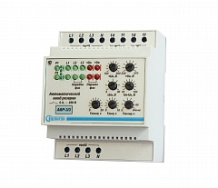
– The AVR block is executed in the case for installation on a DIN lath. – On the forward panel of the block there are handles of regulators of installation of an operating mode of the relay and indicators of a condition of a network. – In the top and lower part of the block there are terminal blocks for connection of the block. Power supply of the block is carried out from the phase L1 "INPUT 1" (the main input) and from the phase L1 "INPUT 2" (reserve input).
The device of automatic input of a reserve with microprocessor management is intended for switching of loading from the main input on reserve at accident emergence. It is carried out in 2 options of execution: AVR 3/3 and AVR 3/3-22.
Design of system
– The AVR block is executed in the case for installation on a DIN lath. – On the forward panel of the block there are handles of regulators of installation of an operating mode of the relay and indicators of a condition of a network. – In the top and lower part of the block there are terminal blocks for connection of the block. Power supply of the block is carried out from the phase L1 "INPUT 1" (the main input) and from the phase L1 "INPUT 2" (reserve input).
Technical characteristics
Warranty period – 2 years.
Preparation for operation and operation
Before operation it is necessary to study the maintenance instruction of the AVR block .
To install the block in an electroboard on a DIN lath.
To make connection of a controlled network of the main and reserve input, chains of management and the alarm system according to marking: L1, L2, L3 "INPUT 1" – phases of the main input; L1, L2, L3 "INPUT 2" – phases of reserve input; N – a neutral (the general for the main and reserve inputs); COM – the switching contact; NO – normally opened contact; NC – normally closed contact - for the P1 and P2 relay. Section of the connected wires has to be not less than 1,0 mm. quarter.
To expose necessary parameters of a controlled network.
To make connection at the de-energized inputs of a network!
It is forbidden to open the block which is energized networks.
| Characteristic |
Value |
| Rated working voltage | 220/380 V, 50 Hz |
| Top threshold of emergency value of tension (phase) «U top» min/max |
230/270 V |
| Lower threshold of emergency value of tension (phase) «U lower» min/max |
150/200 V |
| Hysteresis of the lower threshold "ΔUн" min/max |
5/30 V |
| Phases distortion «U hight-U low» min/max |
10/100 V |
| The switched contact current (AC1 of 250 V) of max |
7 А |
| Overall dimensions of the block |
71х90х60 mm |
| Weight, no more |
0,3 kg |
Warranty period – 2 years.
Preparation for operation and operation
Before operation it is necessary to study the maintenance instruction of the AVR block .
To install the block in an electroboard on a DIN lath.
To make connection of a controlled network of the main and reserve input, chains of management and the alarm system according to marking: L1, L2, L3 "INPUT 1" – phases of the main input; L1, L2, L3 "INPUT 2" – phases of reserve input; N – a neutral (the general for the main and reserve inputs); COM – the switching contact; NO – normally opened contact; NC – normally closed contact - for the P1 and P2 relay. Section of the connected wires has to be not less than 1,0 mm. quarter.
To expose necessary parameters of a controlled network.
To make connection at the de-energized inputs of a network!
It is forbidden to open the block which is energized networks.